TechOlympics 2025
This guide is a writeup of the the "Norse IoT Websocket Workshop" session at TechOlympics 2025.
Here is the presentation for the session. These docs go over the same content as the slide deck.
This session fits in a 60 to 90 minute time slot.
Here's the pitch:
Are you interested in building your very own smart device? This session allows you to learn how to build your very own Wi-Fi enabled game controller, and even play Kahoot with it! You'll be able to get hands on with real Internet of Things technologies, including ESP-32 (like Arduino) microcontrollers. This session will focus on wiring the devices, and no prior coding or electronics experience is required, members from the Norse IoT Club at Northern Kentucky University will be there to walk you through every part of the process.
So, what is IoT?
The Internet of Things (IoT) describes the network of physical objects — "things" — that are embedded with sensors, software, and other technologies for the purpose of connecting and exchanging data with other devices and systems over the internet.
IoT Devices range from ordinary household objects to sophisticated industrial tools.
Oracle estimates there will be 10 billion connected IoT devices today; 22 billion by 2025.
What are we using?
We're using ESP-32 devices, which strike a good balance between power and cost effiency. ESP-32s are a powerful, lightweight chip, anda re useful for many scenarios. They're Wi-Fi/Bluetooth/Matter enabled allowing for various projects.
What are we building?
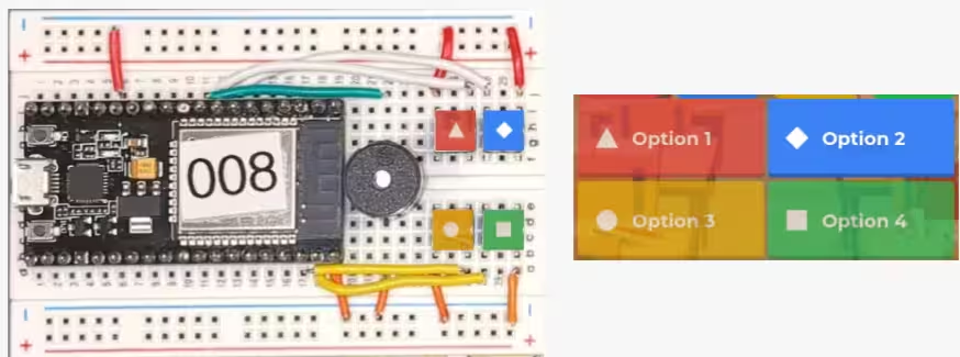
- A Wi-Fi Enabled Game Controller
- Will feature four buttons to send responses and a buzzer to communicate right/wrong.
- Will send data to an open-source Kahoot clone through Websockets.
- Will receive data (correct/incorrect) and make a noise.
The Code
Participants had the code pre-downloaded onto their ESP-32s. If you're looking to follow along at home, you'll need to clone our Rahoot repo, and use Arduino IDE to image your ESP-32 with the client code. For more info, try out our Getting Started guide.
You'll also need to add a secrets.h file to the same folder as the rest of your ESP-32 code.
The content of that file should be the following,
with your Wi-Fi details substituted for the dummy passwords shown here:
You'll also need a webserver running our fork of Rahoot. Follow the repo's Getting Started guide for more information. The Rahoot server receives data over Websockets and displays it on a website.
The Hardware
- 1x ESP-32
- 1x Breadboard
- 1x Buzzer
- 4x Button
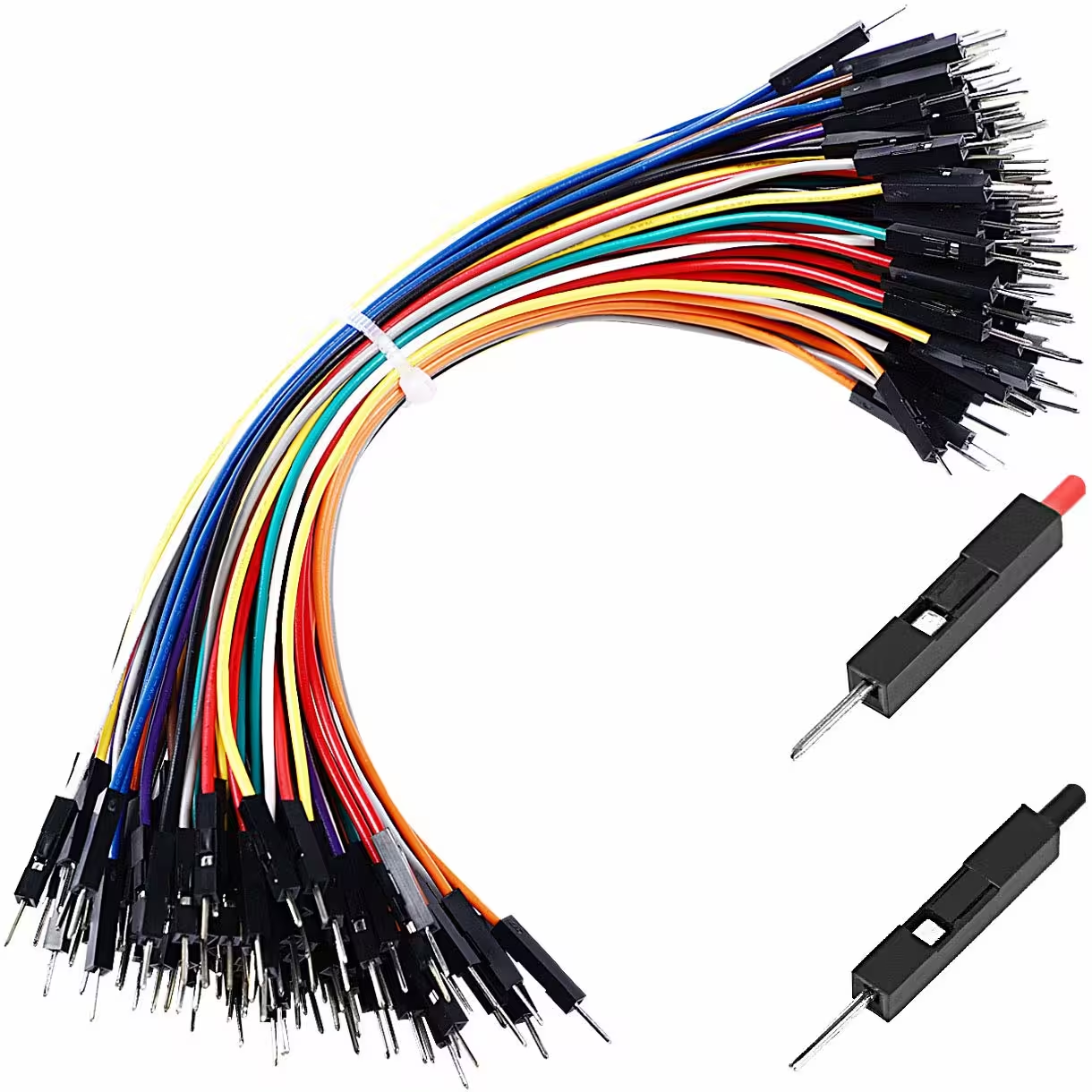
- 1x Jumper Wires
Wires
Wires are used to connect one point to another.
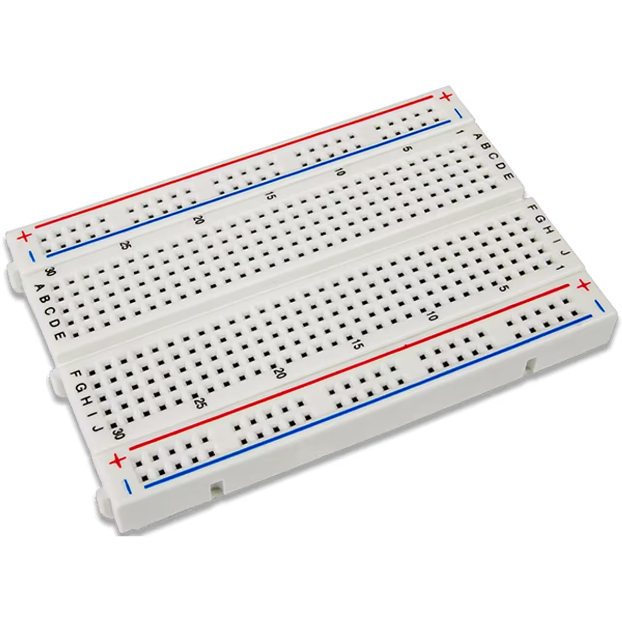
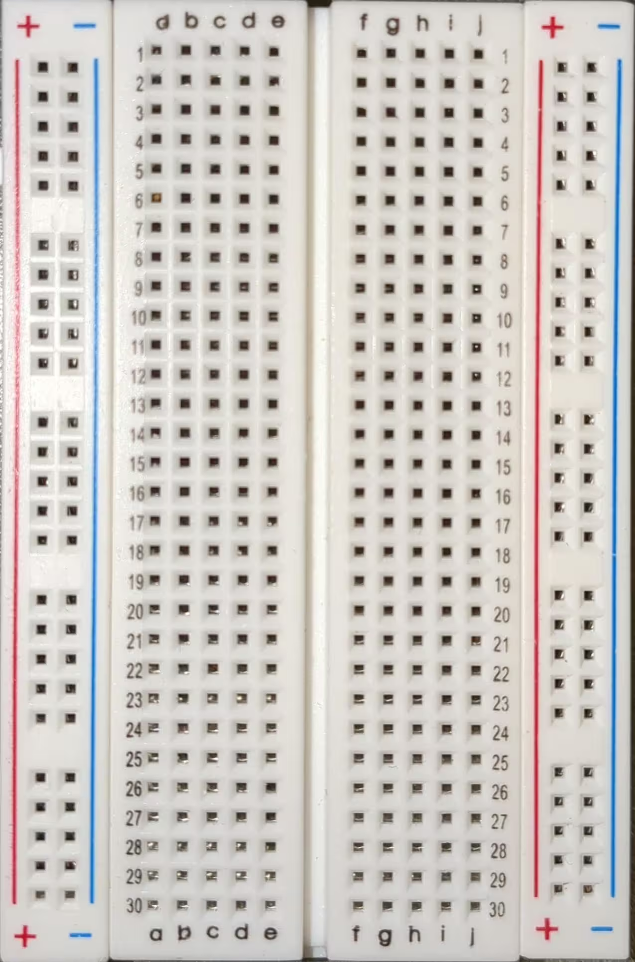
Breadboards
Breadboards allows for easy and adaptable assembly of the microcontroller with input and output devices. Vertical rails, on the left and right sides, connect vertically, and horizontal rails, in the center, connect horizontally.
We'll use one breadboard.
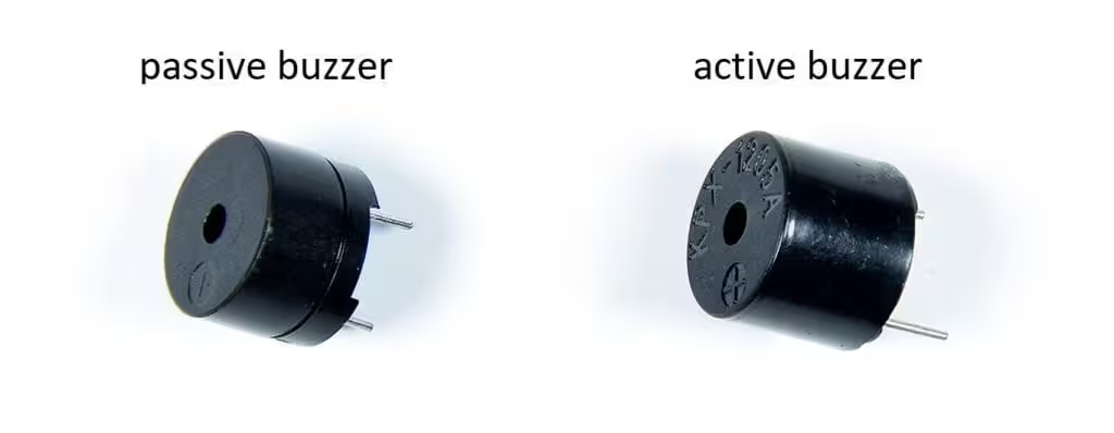
Buzzer
Passive buzzers can play tones! (Active buzzers cannot play tones)
We'll use one passive buzzer.
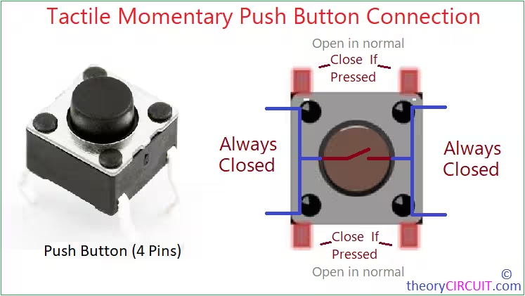
Button
Buttons are, well, buttons! Pressing them sends a signal that the ESP can read.
We'll use four buttons.
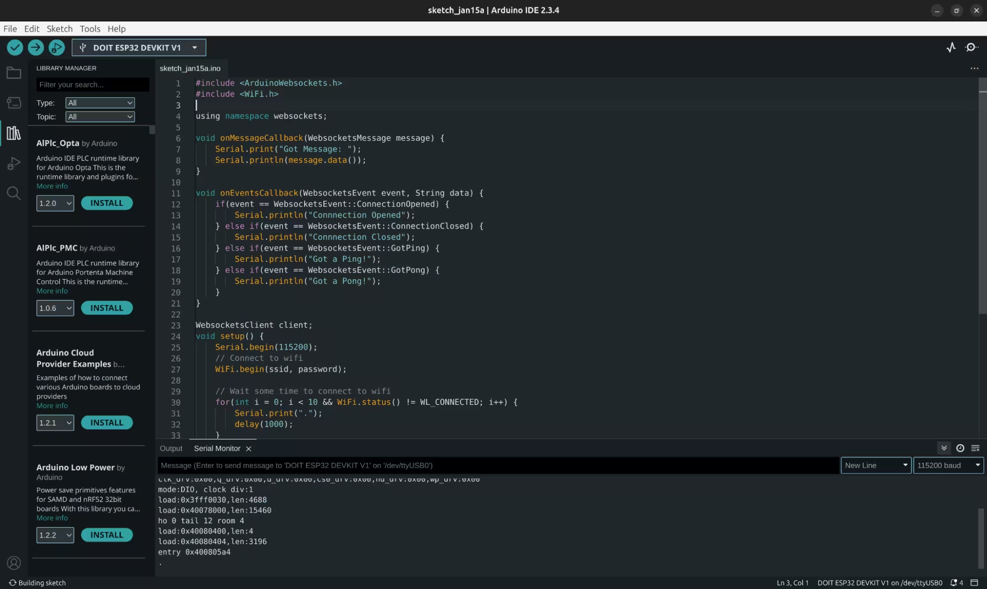
The Software
Arduino Software
As mentioned, the ESP-32s are running C++ code that reads data from buttons and sends the data over Wi-Fi through Websockets.
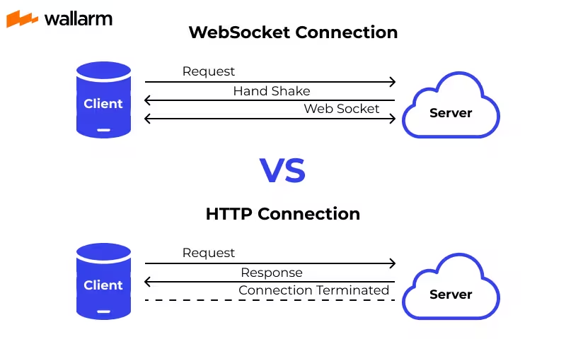
Websockets
Websockets are an API that allows for a client and server to maintain constant communication. Websockets are used in applications like…
- Discord, to allow real time communication between you and your friends
- Minecraft server consoles, to get live updates on your server.
Let's build it!
Step 1: Pull out the breadboard
Go ahead and pull out your breadboard. This will be the base for your project.
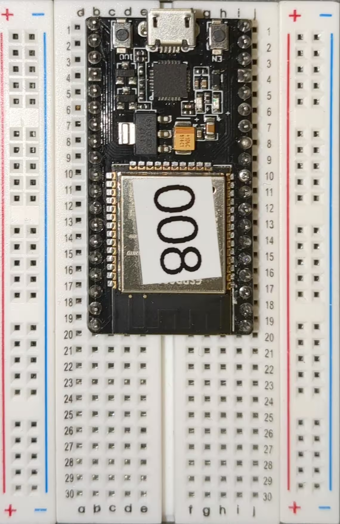
Step 2: Put on ESP-32
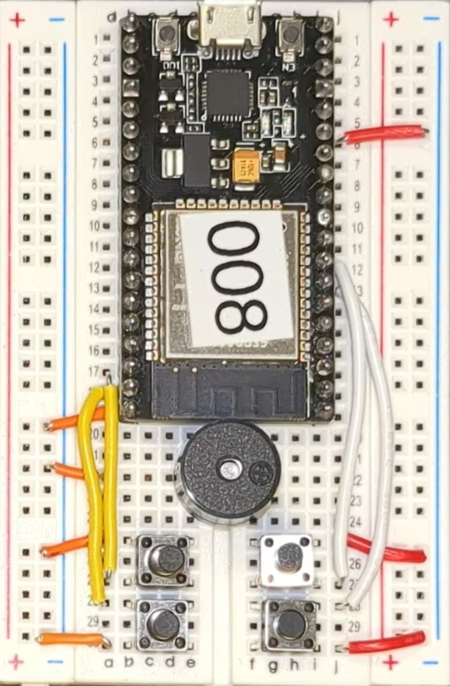
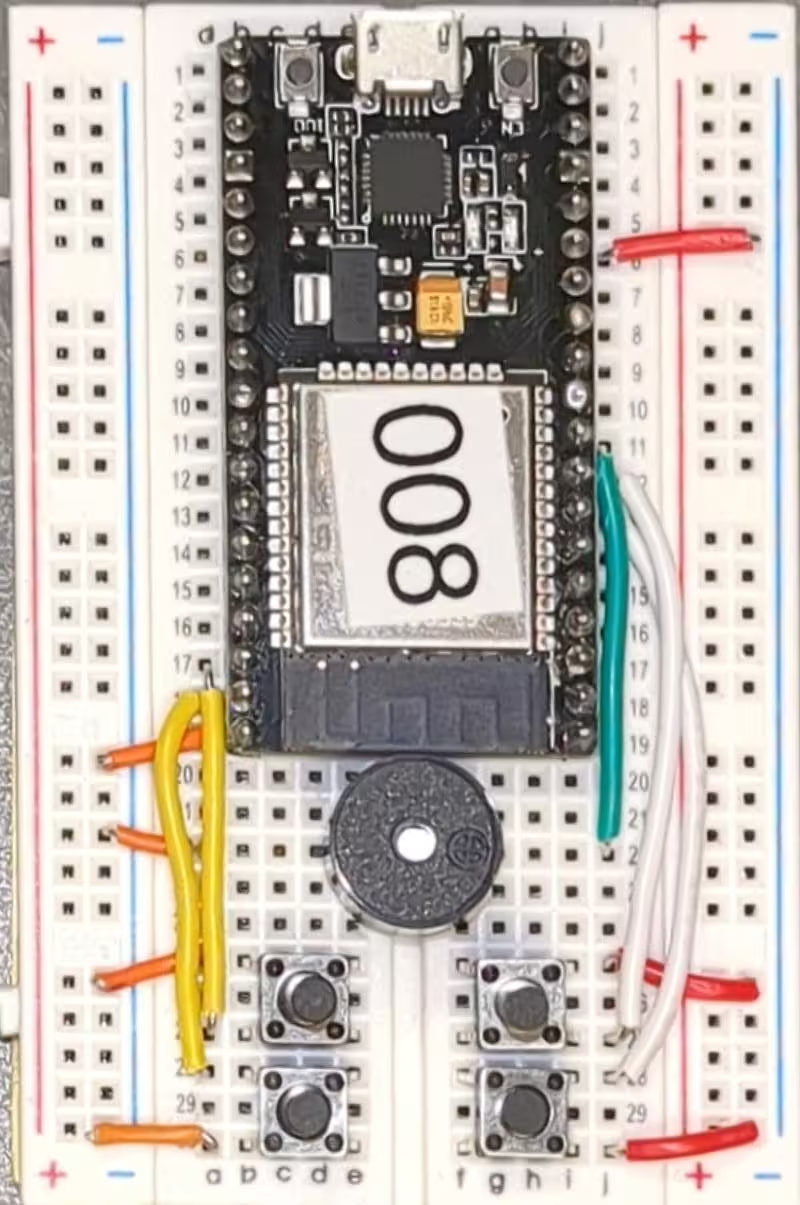
Insert the ESP-32 into the breadboard. The bottom of the ESP-32 (the side with the USB port), should be aligned with row 1, with one corner on column b and the other corner on column i. Do not force it. There is potential to break a pin.
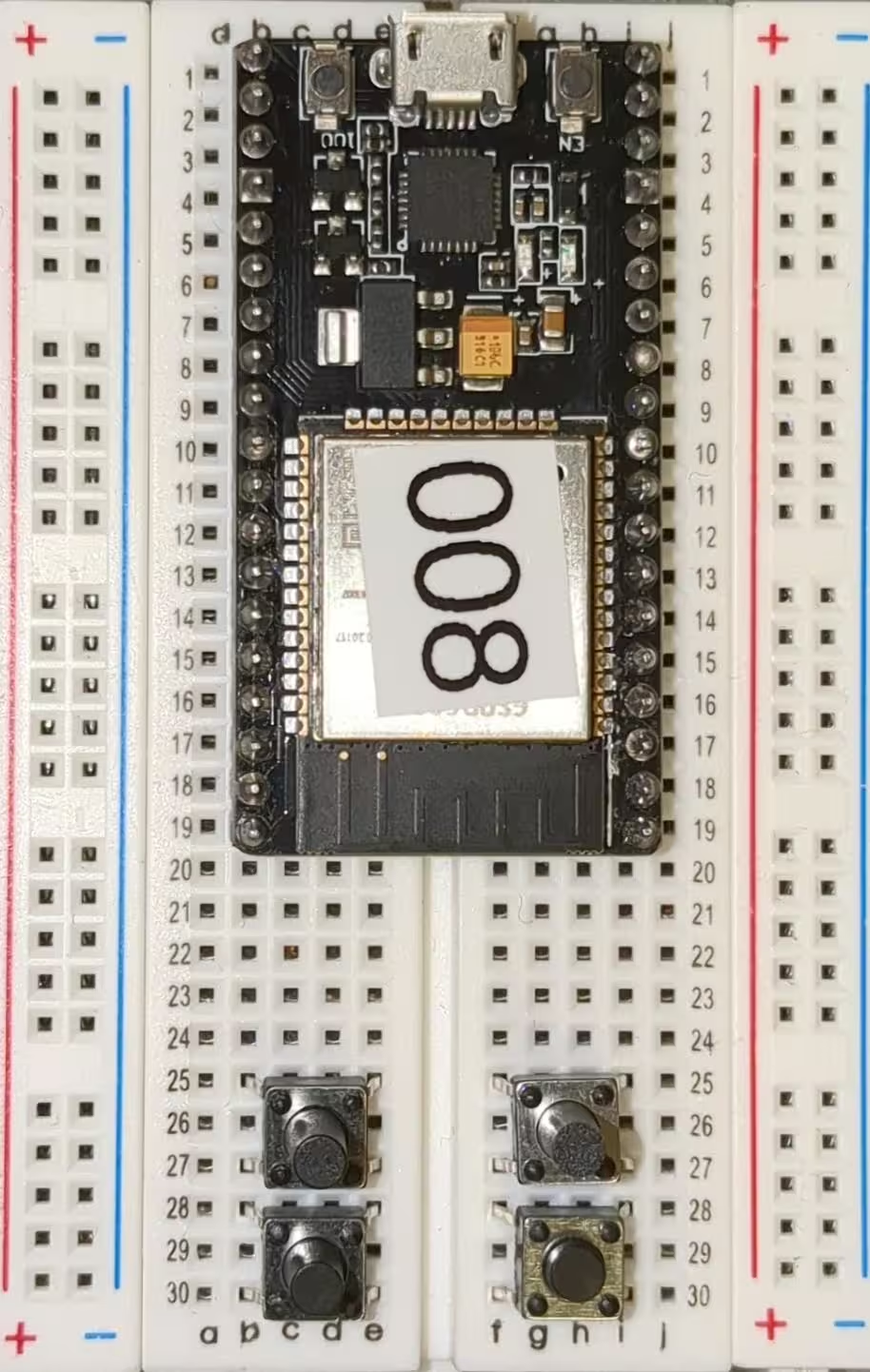
Step 3: Put on Buttons
Take the buttons one step at a time. The pins on the buttons are quite delicate, and while you should avoid breaking them if possible, do not be surprised if one or two are snapped.
- Insert your first button with the top left corner at b25, bottom left corner at b27, top right corner at e25, and bottom right corner at e27.
- Insert your second button with the top left corner at b28, bottom left corner at b30, top right corner at e30, and bottom right corner at e30.
- Insert your third button with the top left corner at f25, bottom left corner at f27, top right corner at i25, and bottom right corner at i27.
- Insert your fourth button with the top left corner at f28, bottom left corner at f30, top right corner at i30, and bottom right corner at i30.
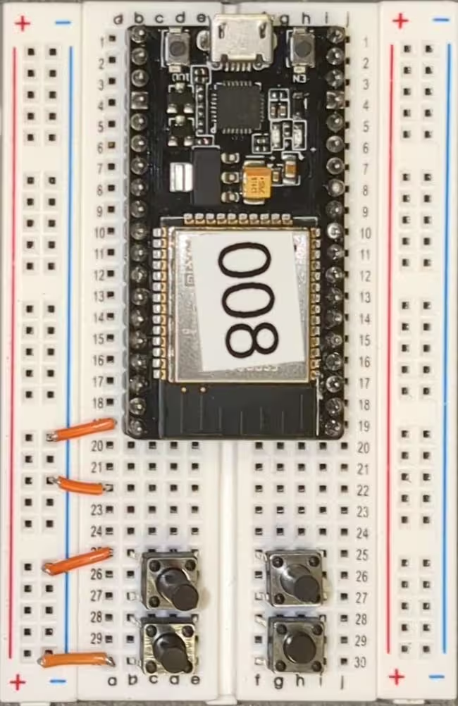
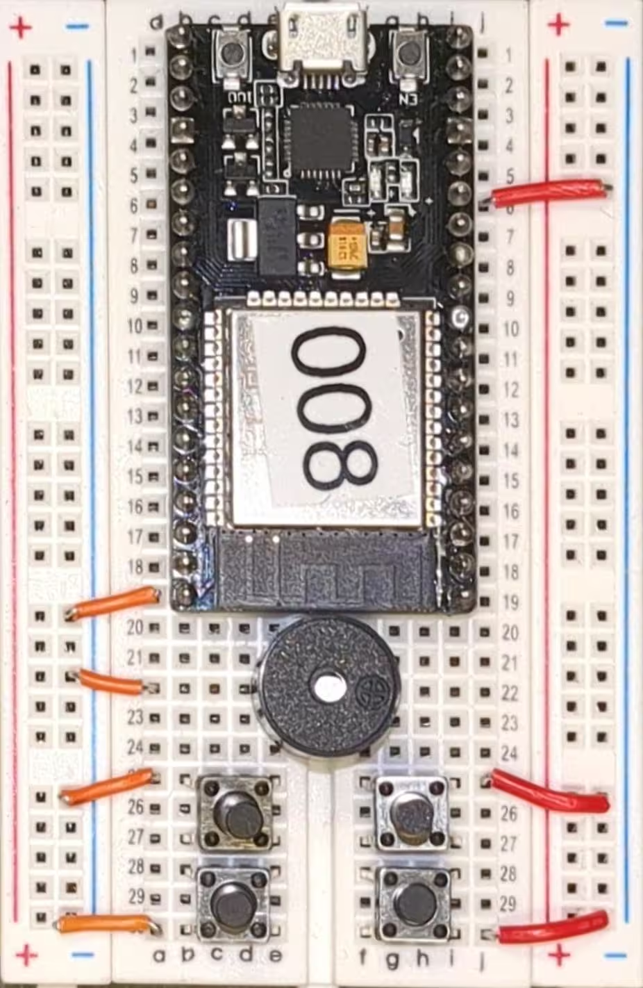
Step 4: Attach Ground Wires
We'll then move on to wiring up ground wires. Ground wires are used to ground our buttons, giving them a baseline reading of zero to read off of.
- Wire from a19 to the left negative rail.
- Wire from a22 to the left negative rail.
- Wire from a25 to the left negative rail.
- Wire from a30 to the left negative rail.
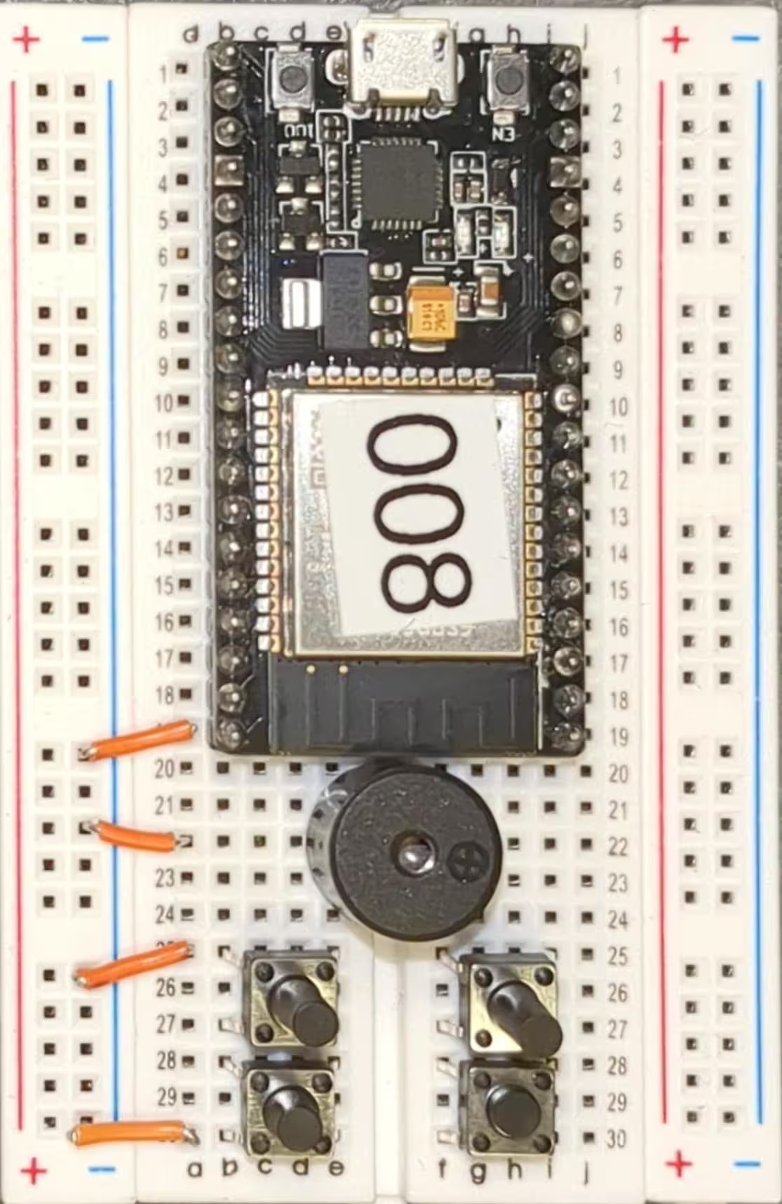
Step 5: Attach Buzzer
We'll now go ahead and attach the buzzer. The buzzer has two pins and we'll place the buzzer on slots e22 and f22, straddling the divide between the two sections of breadboard.
Step 6: Attach Ground Wires
We have a few more ground wires for the other side.
- Wire from j6 to the right negative rail.
- Wire from j25 to the right negative rail.
- Wire from j30 to the right negative rail.
Step 7: Attach Data Wires
Now we move on to attaching data wires. The ESP-32 will use this to read the data from the buttons.
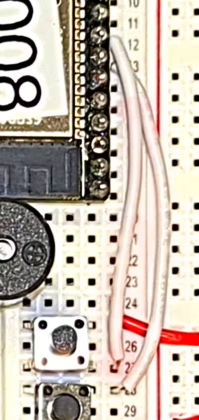
- Wire from a18 to a28.
- Wire from a17 to a27.
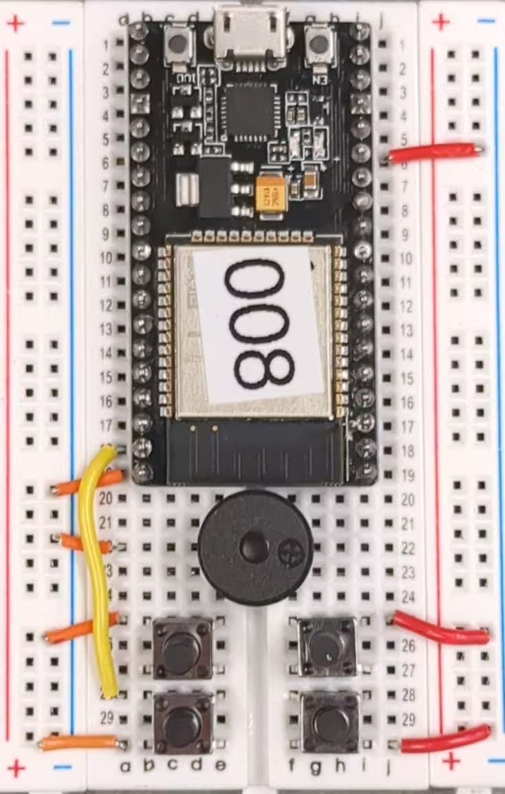
Step 8: Attach Data Wires
Now we move on to attaching data wires. The ESP-32 will use this to read the data from the buttons.
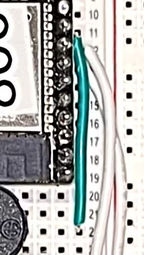
- Wire from a13 to a28.
- Wire from a12 to a27.
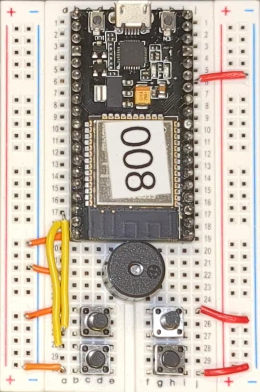
Step 9: Attach Power Wire
Now we can wire up power for our buzzer. The ESP-32 provides five volts of power on pin a11, that we will provide to our buzzer.
- Wire from a11 to a22.
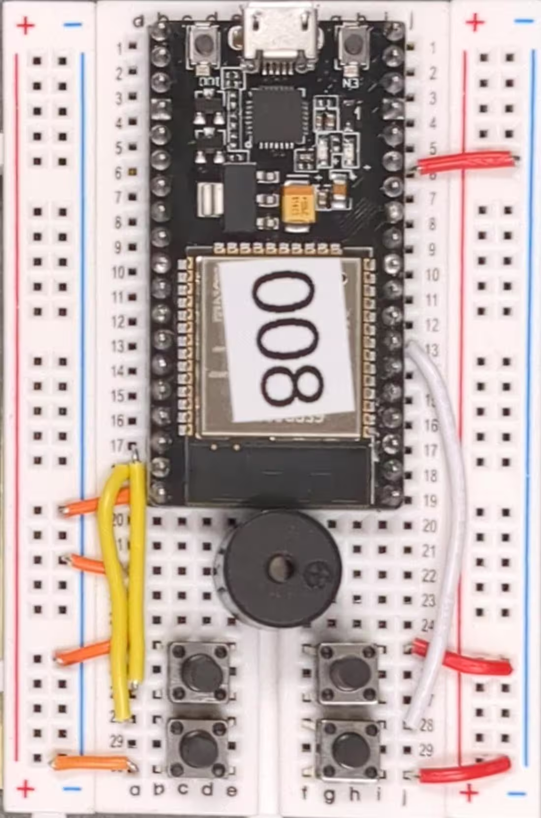
Step 10: Play!
You can now plug in your ESP-32 to power and it will connect to Wi-Fi and then to the Rahoot server. If you rotate your breadboard so the USB port is facing to the left, you can use the buttons to play Rahoot.